|
|
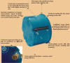
ADVANTAGES OF
HOLLOW WALL BOXES |
|
|
|
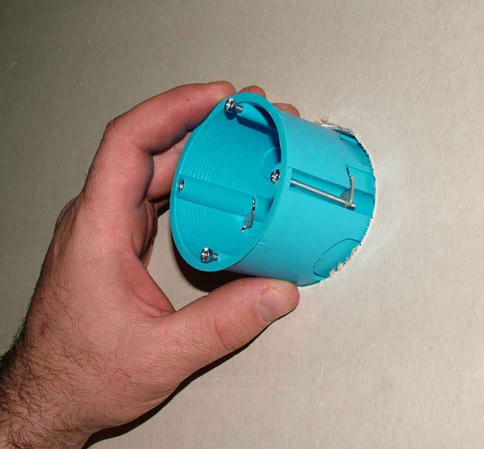
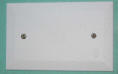
MOUNTIG OF SM 68x40, SM
68x55 and SM 80x45 HOLLOW WALL BOXES |
|
|
|
|
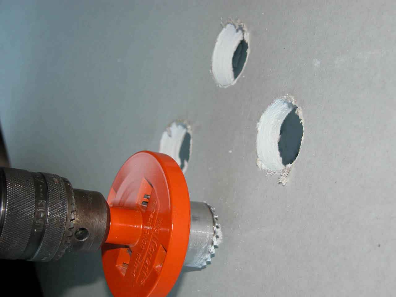
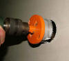
Drill a borehole of 68mm, for SM 80x45 a borehole of 80mm. |
|
|

|
|
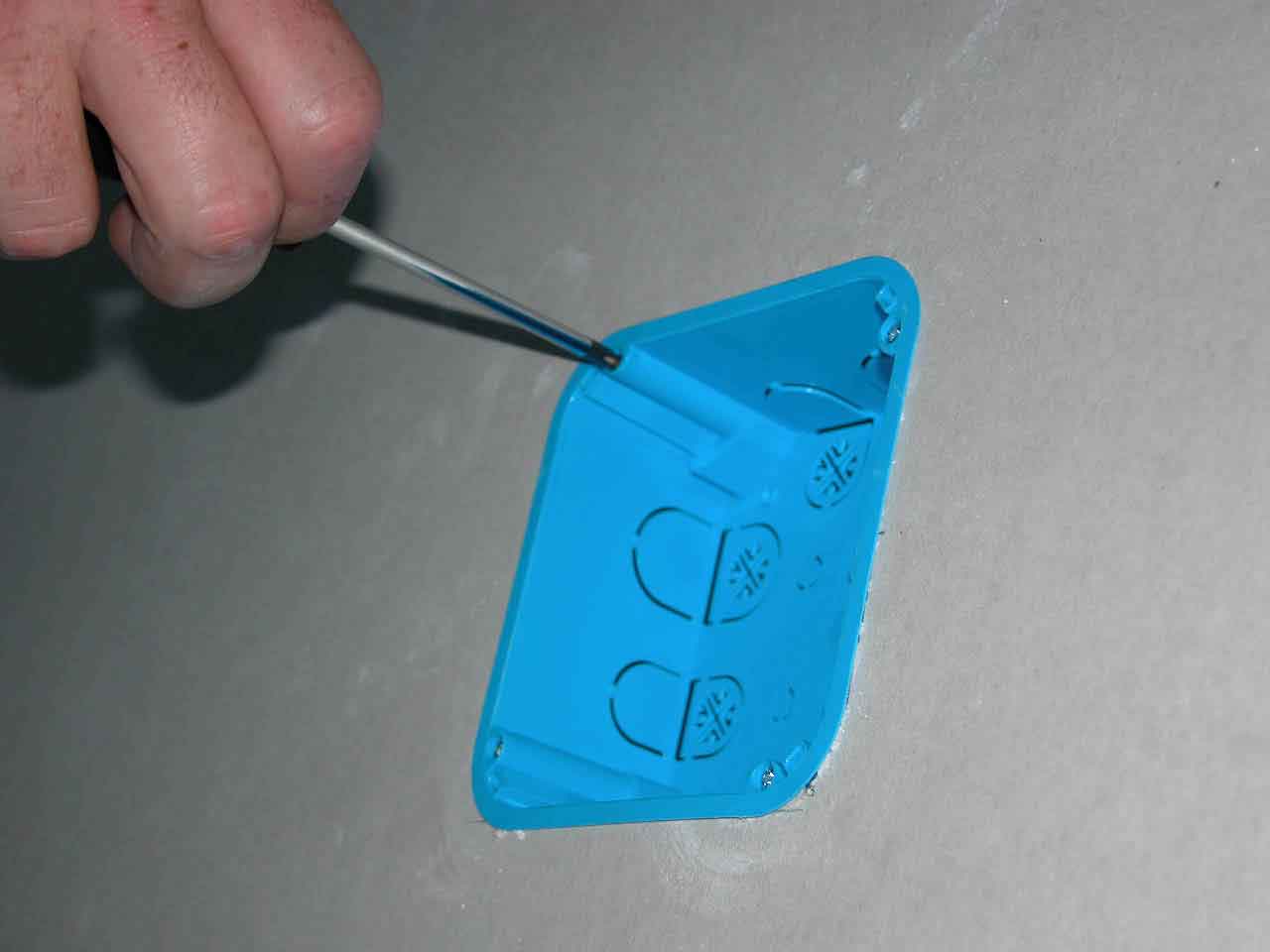
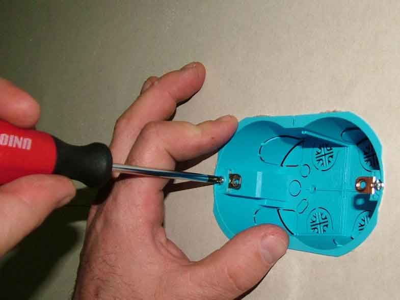
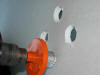
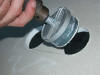
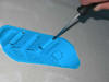
By turning the screwdriver to the right the metal plate automatically turns from its bed and approaches the wall with the fast three-step thread. Thereafter tighten the screw with moderate force to avoid any deforming of the box edge. |
|

|
|
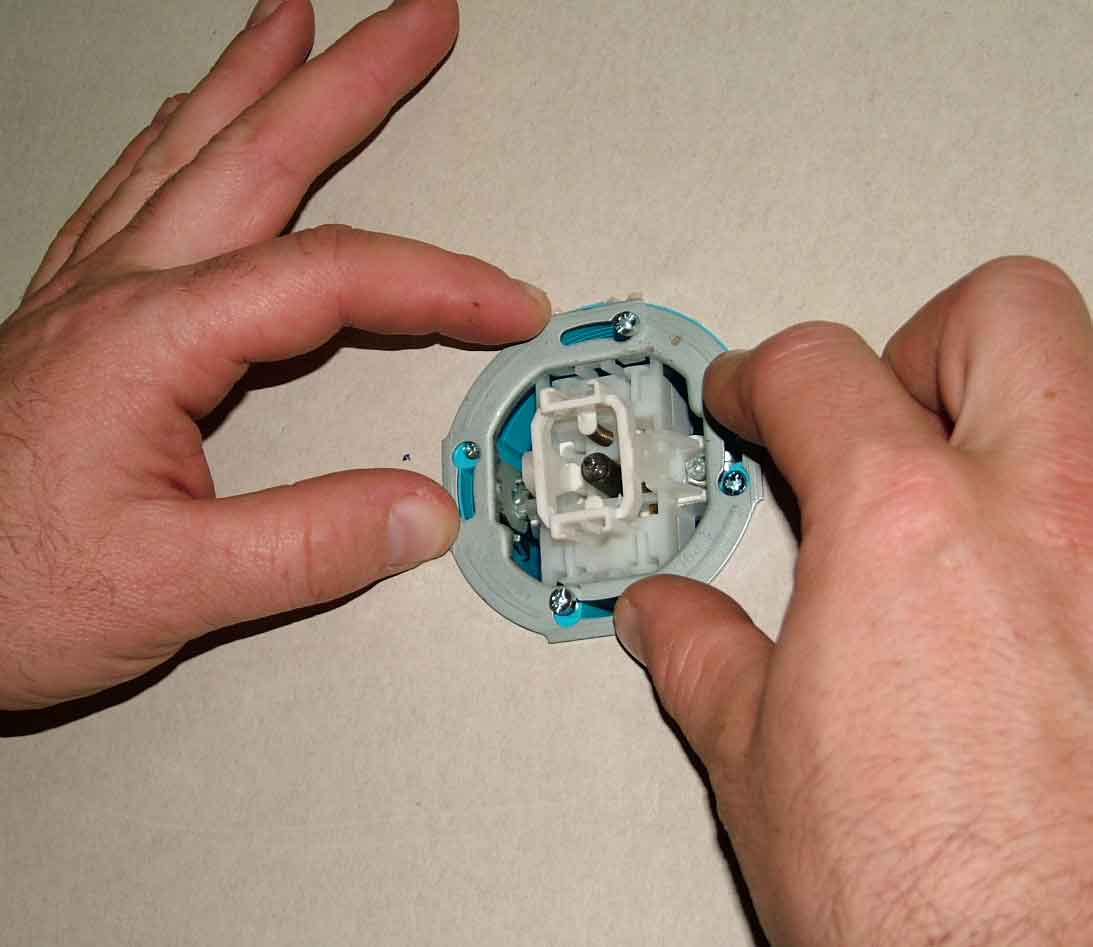
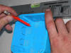
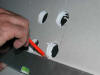
Once the socket or the switch is connected with conductors, put it into the box, adjust the horizontal position and proceed to tightening. |
|
|

|
|
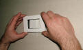
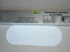
Cover the SM 80x45 distribution box with the SM 78-80mm cover. |
|
|
|
|
MOUNTING OF VSM 105x105 HOLLOW WALL DISTRIBUTION
BOXES |
|
|

|
|
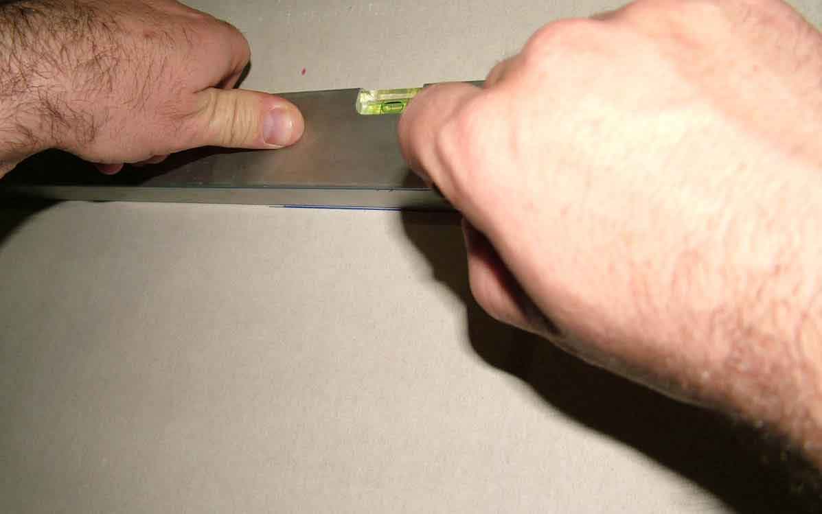
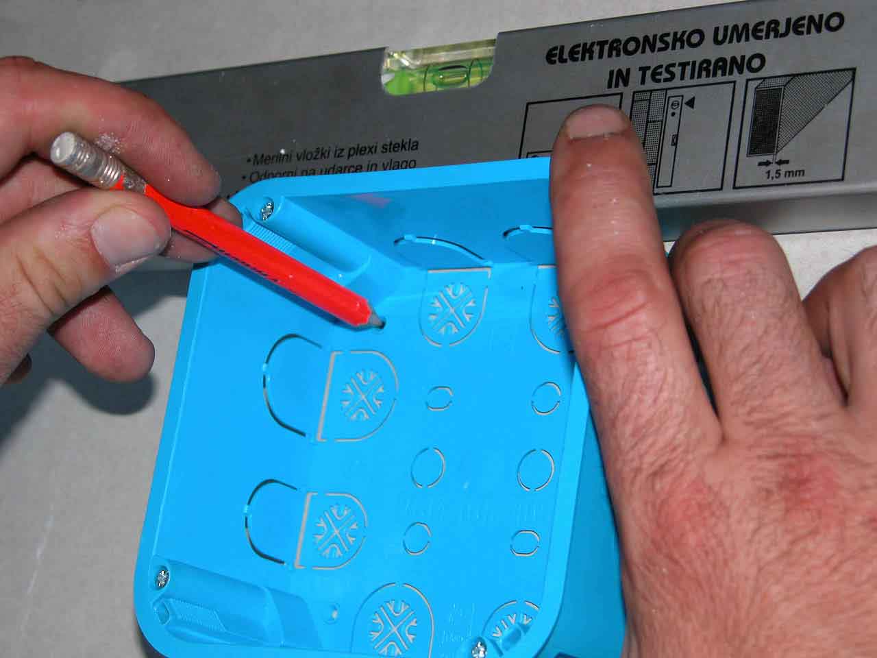
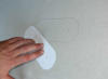
Marking by applying the enclosed pattern:
draw the initial line by means of a spirit level. |
|

|
|
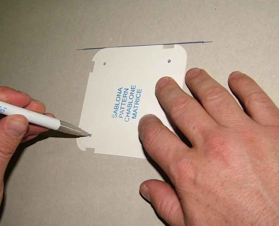
Place the pattern along the initial line, wipe it and mark the center of each 35mm borehole through the holes of the pattern. |
|
|
|
|
|
|
|
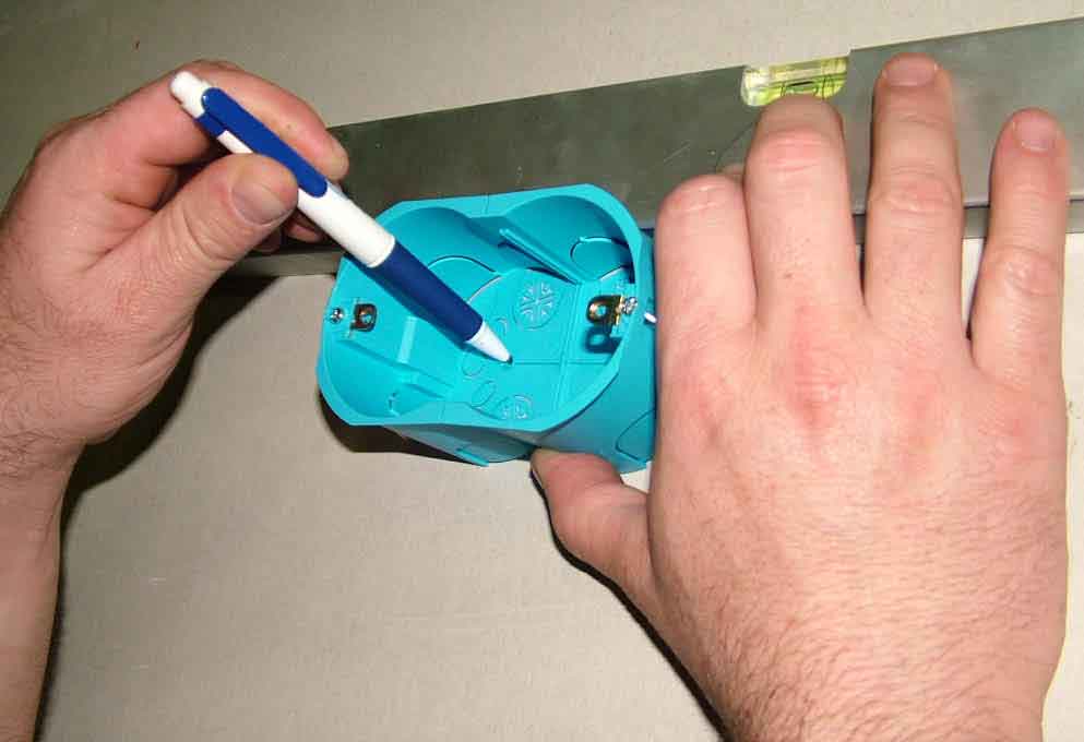
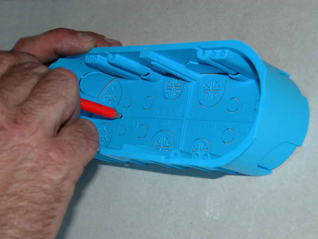
Marking without the pattern:
position the box against the wall by means of a spirit level. Mark the center of each 35mm borehole through the holes of the box. |
|
|
|
Drill 4 marked boreholes of 35mm. |
|
|
|
Draw the lines between the boreholes. |
|

|
|
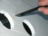
Cut the wall along the lines and if necessary, correct the edge with a file. |
|

|
|
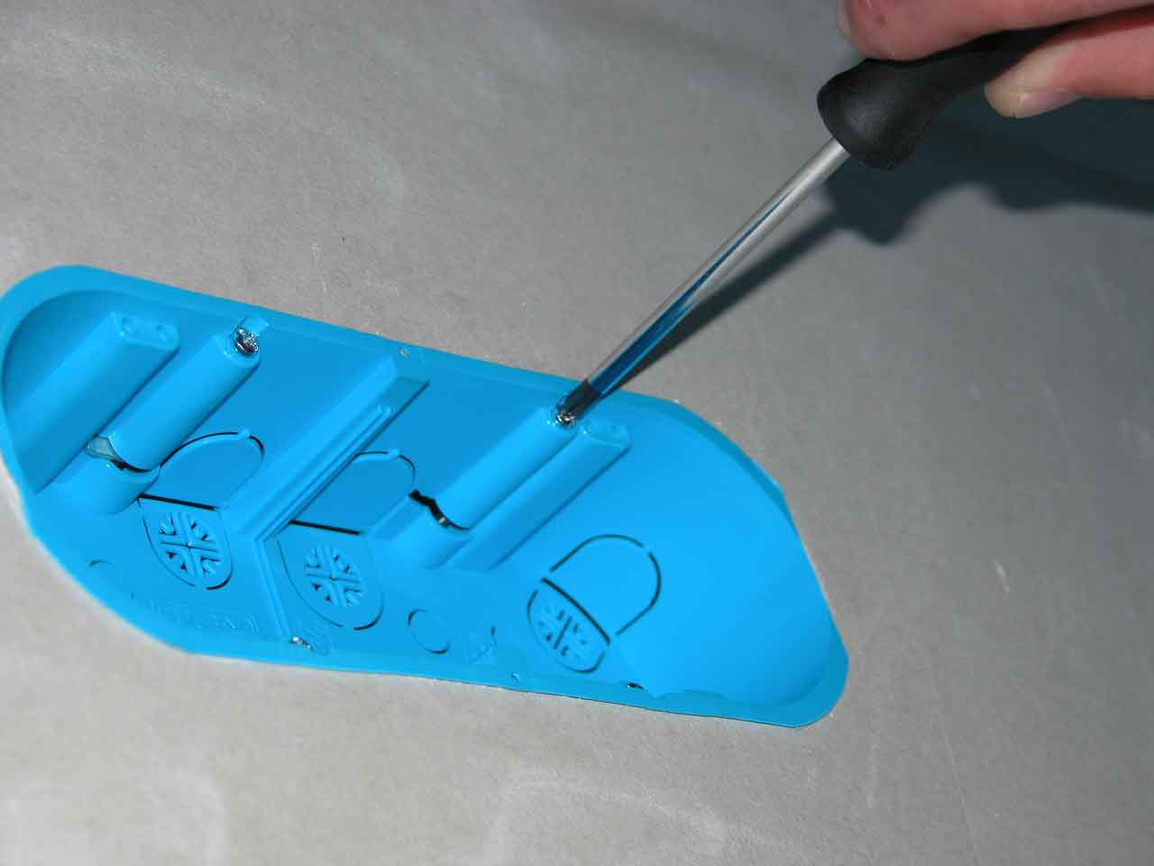
By turning the screwdriver to the right the metal plate automatically turns from its bed and approaches the wall with the fast three-step thread. Thereafter tighten the screw with moderate force to avoid any deforming of the box edge.
|
|
|

|
|
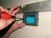
Once the connection in the box is completed, cover the box with a screwless cover that allows for additional tightening of screws, if required. The cover is very thin and fits snuggly to the wall, hereby enabling slight adjustment to the horizontal level. |
|
|
|
|
MOUNTING OF VM3 and VM4 HOLLOW WALL MODUL BOXES |
|
|

|
|
Position the box against the wall by means of a spirit level. Mark the center of each 35mm borehole through the holes of the box.
|
|

|
|
Drill 2 marked boreholes of 68mm. |
|

|
|
Correct the edge with a file. |
|

|
|
By turning the screwdriver to the right the metal plate automatically turns from its bed and approaches the wall with the fast three-step thread. Thereafter tighten the screw with moderate force to avoid any deforming of the box edge.
|
|
|
|
Position the switch holder on the box by using a spirit level and tighten it. |
|
|
|
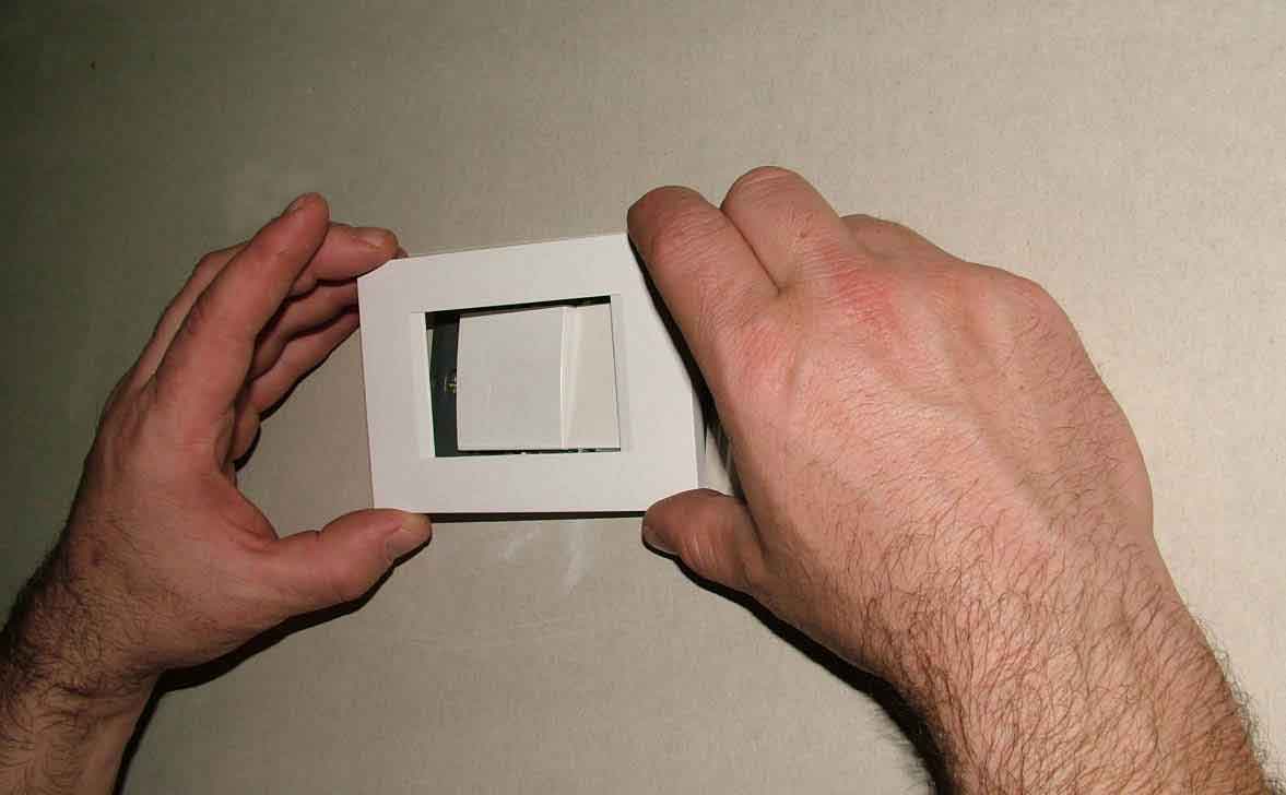
Once the sockets or the switches are connected, insert them into the box and cover them with a decorative mask. |
|
|
|
If a VM3 or VM4 box is to be used as a distribution box and/or the box temporarily contains no switches, cover it with the PM3/VM3 or PM4/VM4 cover. |
|
|
|
|
MOUNTING OF VM7 HOLLOW WALL MODUL BOXES |
|
|
|
|
Marking by applying the enclosed pattern:
Place the pattern horizontally by means of a spirit level. |
|
|
|
Wipe the pattern and mark the center of each 68mm borehole through the holes of the pattern. |
|
|
|
|

|
|
Marking without the pattern:
position the box against the wall by means of a spirit level. Mark the center of each 68mm borehole through the holes of the box.
|
|
|
|
Drill 2 marked boreholes of 68mm. |
|
|
|
Cut straight lines between the boreholes. |
|
|
|
By turning the screwdriver to the right the metal plate automatically turns from its bed and approaches the wall with the fast three-step thread. Thereafter tighten the screw with moderate force to avoid any deforming of the box edge.
|
|
|
|
|
|
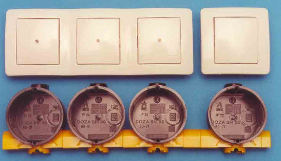
ASSEMBLING OF SM 60-01
and SM 60-06 FLUSH-MOUNTED BOXES |
|
|
|
|

|
|
|
|
|
|
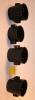
SM 60-01 and SM 60-06 boxes may be assembled in any combinations. |
|
|
|
|
|
|
|
|
|
|
|
|
For vertical mounting of switches in a frame simply join the boxes one into another and add the SM 60-03 extension piece. |
|
|
|
|
|
|
|
|
|
|
|
|
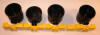
For cross-linking of boxes for switches or sockets in a frame use the SM 60-04 linking element. |
|

|
|
If the switches are separated one from another, insert between the linking elements the SM 60-03 extension piece that provides for the standard 91mm centerline spacing. |
|
|
|
| |
|
|
|
top |